mico lock wiring diagram
Diagrams are arranged such that the power B. Wire the 5700 to the 3100 transmitter55.

Db 9 Male And Female Connector Robotics Projects Information Technology Computer Science
John Deere 310SG and 315SG Backhoe Loader workshop service repair manual includes.

. Abryll EM 3Abryll EM 1 SATEAbryll EM 3 SATE The MICO Abryll Single Point Electro-Mechanical Range to be used with any 12v Access Control System. Numbered table of contents easy to use so that you can find the information you need fast. 30mm bolt projection 25mm bolt throw.
It can be configured to offer full entry in and out or entry in with Emergency Escape out when fitted with our SATE option. Lever Locks are designed to supplement your standard parking brake by utilizing the hydraulic service brakes. Ratings gained on selected locks on selected doorsets.
Complete technical manual with Electrical Wiring Diagrams for John Deere 310G Backhoe Loader with workshop information to maintain diagnose and service like professional mechanics. The MICO Abryll Range has established itself as the most approved Single Point Locking Range for high security applications. Numbered table of contents easy to use so that you can find the information you need fast.
In MICO we stock. MICO designs and manufactures hydraulic components controls and brake systems primarily for off-road markets. Problem in the wiring.
Contents Installation Manual September 2020 MMI-20027478. Edmonton Brake Clutch Ltd. Supplied as standard operation of Access Control in and out for full audit trail.
Bleeding The 691 System must only be installed by someone with. Switch the 690 System to the off position. John Deere 310G Backhoe Loader workshop diagnosois test technical manual includes.
Is the 1 MICO distributor across Canada. Manufactured from Stainless Steel as standard the Abryll Range offers a robust high security solution for even the harshest environments. The switch is not electrically opening while pressure is released.
Complete Diagnosis Operation and Test Service Manual with Electrical Wiring Diagrams for John Deere 410G Backhoe with all the shop information to maintain test and service like professional mechanics. John Deere 410G Backhoe Loader workshop Operation and Test repair manual includes. They are manually operated one-way check valves which lock fluid under pressure in the selected brakes.
Coded wiring diagrams and a specific 691 ModelsReplacement Parts Table are also included. 1 Ground 2 Audio 3 Transmit 4 Receive 5 BT Button 6 BT Microphone. 1 Before you begin.
Using a flat-head screwdriver loosen the four captive screws that secure the display cover to the housing. Hand operation leaves the. This manual provides information on planning mounting wiring.
Complete Operation Test manual with wiring diagrams for John Deere 310SG and 315SG Backhoe Loader with all the shop information to maintain diagnoseand rebuild like professional mechanics. 1 UltraShift DM3 6-Speed Wiring Diagram with Analog Shifter UltraShift DM3 6-Speed Wiring Diagram with Analog Shifter Gear select motor Rail select motor Electric shifter A B A B Rail select sensor Gea r10 select sensor Input shaft speed sensor Output shaft. Disconnect the violet control module wire from the red wire on the low pressure switch.
Tested and approved on selected single and double doorsets to LPCB SR 2345 6. Configuration and Use Manual MMI-20019043 Rev AB March 2018 Micro Motion Model 2700 Transmitters with Analog Outputs Configuration and Use Manual. In order to effectively use Chrysler wiring diagrams to diagnose and repair a Chrysler vehicle it is impor-tant to understand all of their features and charac-teristics.
MICO Elite Range is the ideal choice where security is paramount. This unit is handed as per diagram below add code when ordering. The internal Breakdome or external Key.
02-600-001 02-600-002 02-600-016 02-600-029 02-600-033 02-640-123 02-640-124 02-640-125 02-640-126 02-640-135 03-640-131 03-640-199. Option 1 - Push Pad Option 2 - Full Width Push Plate. Numbered table of contents easy to use so that you can find the information you need fast.
AutoShift 18-Speed Wiring Diagram with Push Button Shifter. Chrysler wiring diagrams are designed to provide information regarding the vehicles wiring content. 11 About this document.
MICO 691 Lock System Manual Form Number 81-690-032 This 24-page service manual includes installation operating and trouble shooting information. Although all have been known to work the wirings in this manual are. Wiring 3 Wiring 31 Connect input and output wiring Figure 3-1 shows the location of the wiring terminals on the Model 3350 or Model 3700.
Connect inputoutput wiring to the appropriate terminals on the gray terminal block. 4 Micro Motion 5700 Transmitters with Configurable Inputs and Outputs. 81-690-032 Revised 2007-09-06 There are four steps to installing the 691 System.
Astatic Does not assume the responsibility of any damage to either the microphone nor any radio that has been modified to the specifications within this manual. Check the integrity of all wiring connections. Refer to wiring diagram on page 6.
Wiring for the C29 LX MAX and the C29LTDBT. All my wires in my mic broke off and i need to put it back together but i can not find a wire diagram any where for it. Its a 6 pin.
Low pressure switch is inoperative.
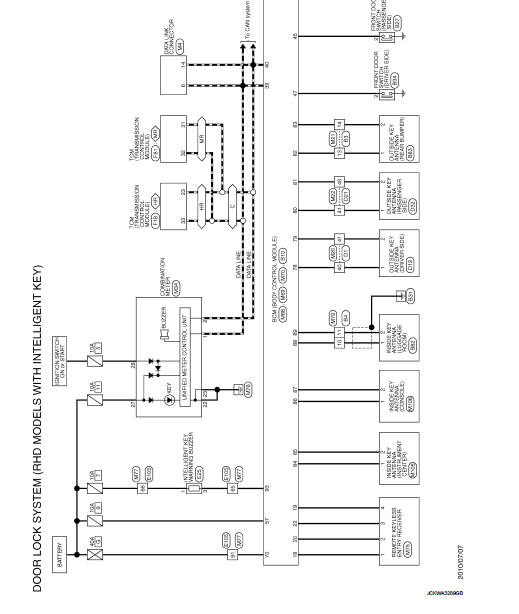
Wiring Diagram Door Lock Type 1 Nissan Juke Service And Repair Manual
How I Did The Mylink Wire Harness Chevrolet Cruze Forums

Mico Product Training Session 9 Hydraulic Brake Locks Youtube

Brklock

Power Door Lock Actuator Wiring Diagram Door Locks Electrical Wiring Diagram Door Switch
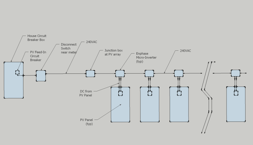
Diy Pv System Installation Wiring

Home Theater Speaker Wiring Diagram Access Control System Access Control Home Security Systems
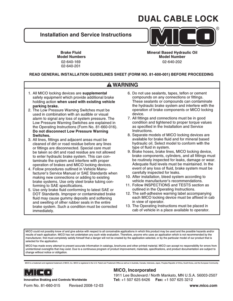
Dual Cable Lock Installation And Service Instructions Manualzz
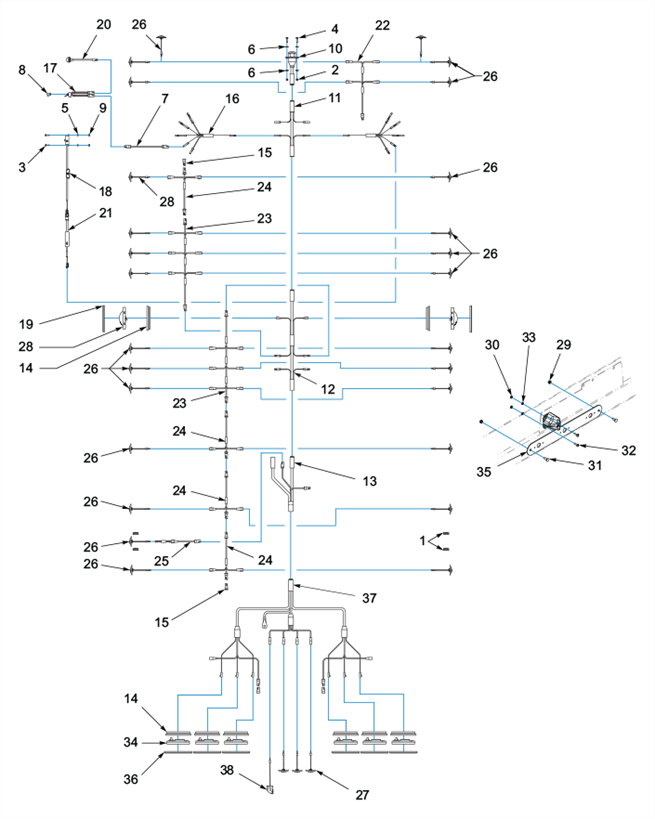
Electrical System

Push Button Ignition Switch Wiring Diagram New Boat Wiring Kill Switch Electrical Wiring Diagram

55 Elegant Viper Remote Starter Wiring Diagram Installation Manual Remote Diagram

Door Access Control System Wiring Diagram Solidfonts Inside The Brilliant Door Access Control System Wiring Diagram With Regard To Your Property Yugteatr Access Control System Access Control Diagram
2
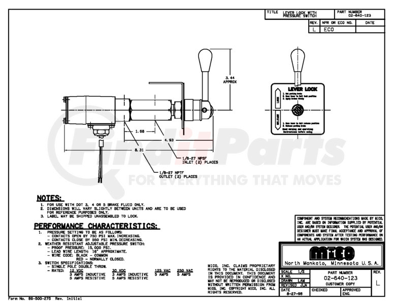
02 640 123 By Mico Hydraulic Brake Lever Lock Brake Fluid Systems Only Without Mounting Bracket

16 Car Center Lock Wiring Diagram Car Diagram Wiringg Net Electrical Wiring Diagram Electrical Diagram Diagram

Control Three Phase Motor Starter With Start Stop Buttons Motor Electrical Panel Control

5 Wire Door Lock Actuator Wiring Diagram Wire Center Best Of Power Door Locks Electrical Wiring Diagram Car Door Lock

Fingerprint Sensor Home Security Systems Biometrics Home Security

Solved I Need A Wiring Diagram For A Maytag Washer Fixya